Field Case 001 · Commercial Water Loss

From hidden-condition screening to exposed-assembly verification.

This case documents a commercial mitigation sequence using thermal screening, comparative moisture measurements, selective demolition, psychrometric monitoring and drying-equipment performance data.

Evidence boundary: Client identity and location are intentionally omitted. These photographs document field conditions and methods. They do not, by themselves, establish cause, insurance coverage, final drying completion or reconstruction outcome.

What this case can teach

Thermal imaging is screening—not proof of moisture

The camera records surface-temperature differences. A localized cool pattern can help direct further investigation, but another measurement or direct observation is needed before calling that pattern moisture.

One meter number is not a diagnosis

Instrument type, selected mode, material, reference conditions and measurement location affect interpretation. The useful question is often how readings compare across an assembly and over time.

Drying is evaluated as a system

Material response, ambient psychrometrics and equipment inlet/outlet performance belong in the same evidence chain rather than being treated as isolated numbers.

The investigation sequence

1

Screen

Visual inspection and thermal imaging locate conditions that deserve closer investigation.

2

Measure

Moisture instruments and comparison points test the working hypothesis rather than relying on appearance.

3

Expose when warranted

Selective removal can reveal insulation, framing, wall cavities and interfaces that are otherwise concealed.

4

Control the drying environment

Airflow and dehumidification create conditions that support evaporation and vapor removal.

5

Monitor performance

Psychrometric and equipment data help determine whether the system is actually changing conditions.

6

Re-measure

Repeat material measurements and field observations are more meaningful than declaring a structure dry because equipment has run for a certain number of days.

Thermal screening and opened assemblies

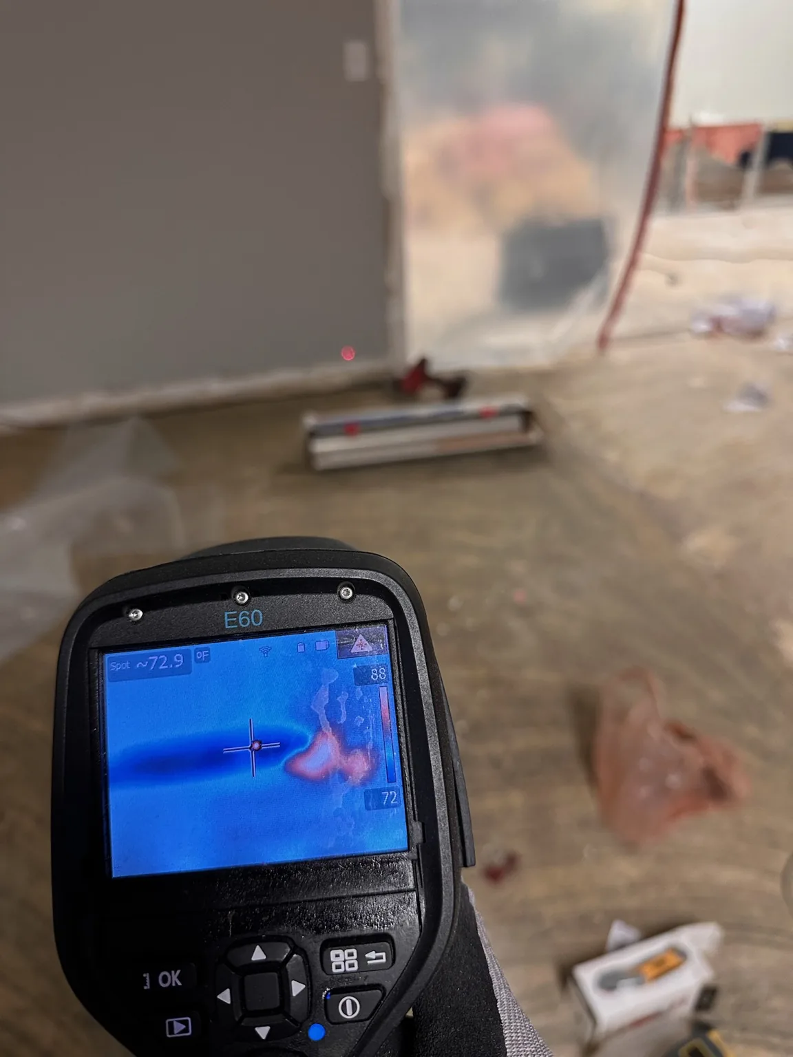
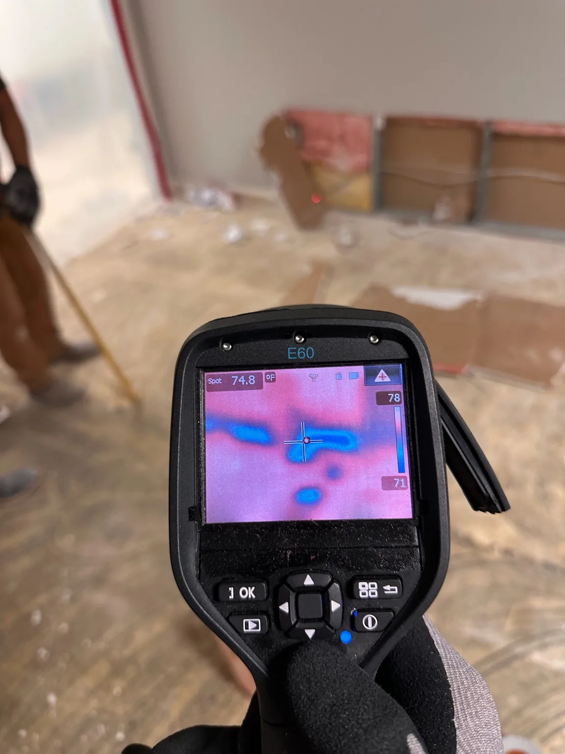
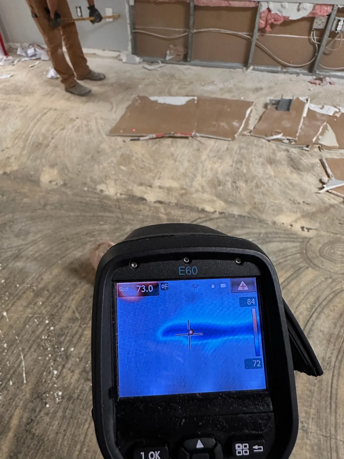
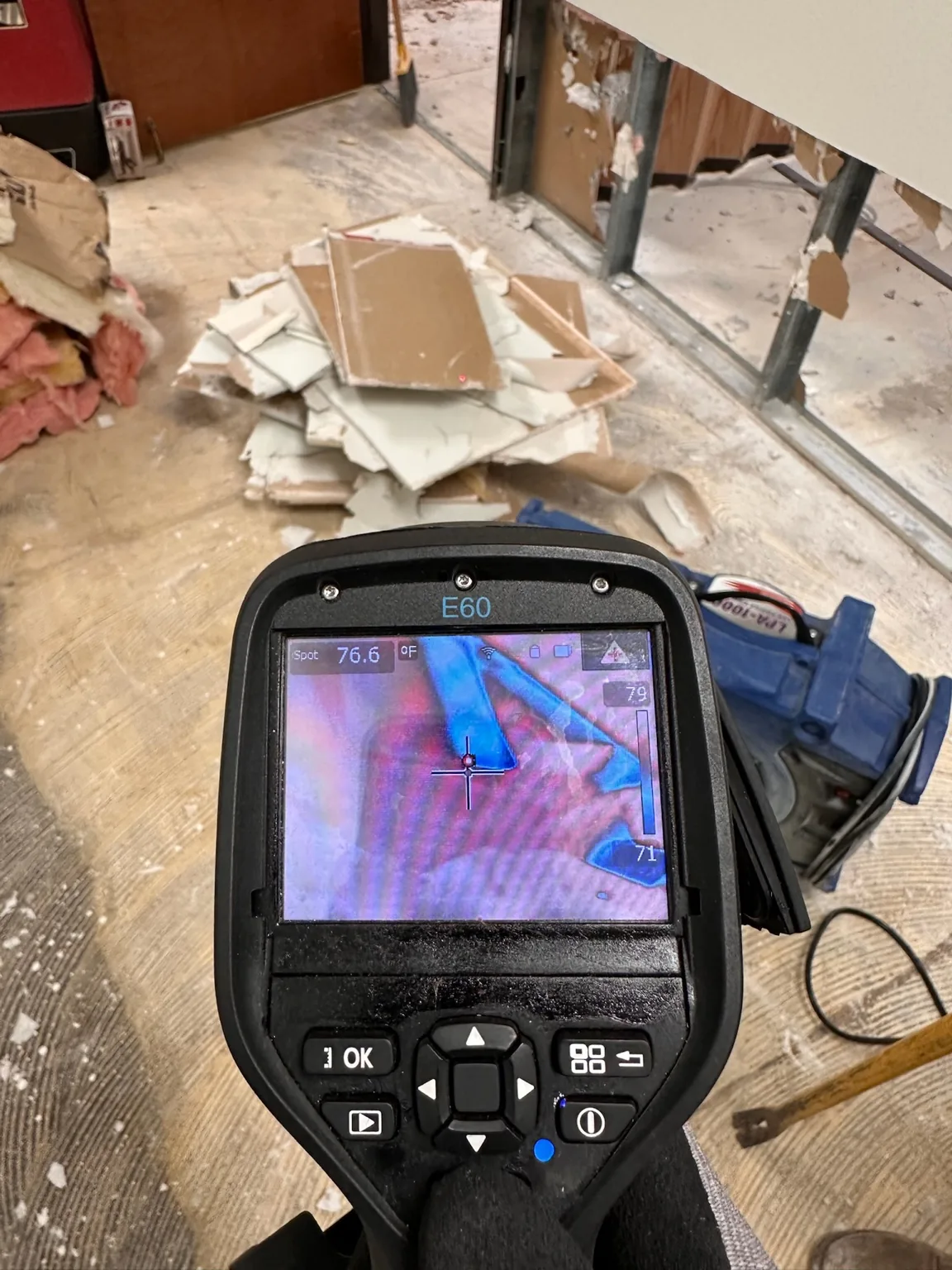
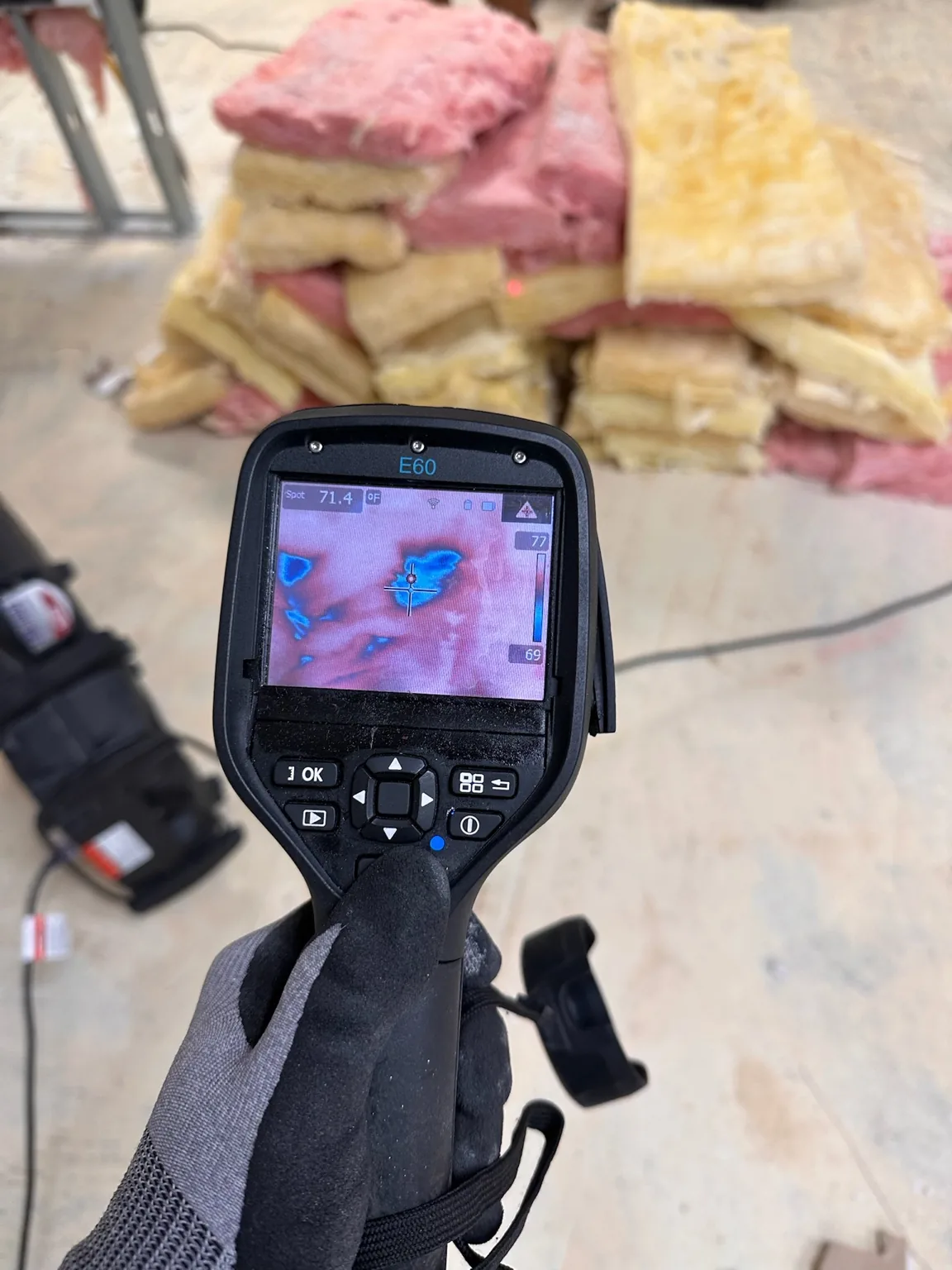
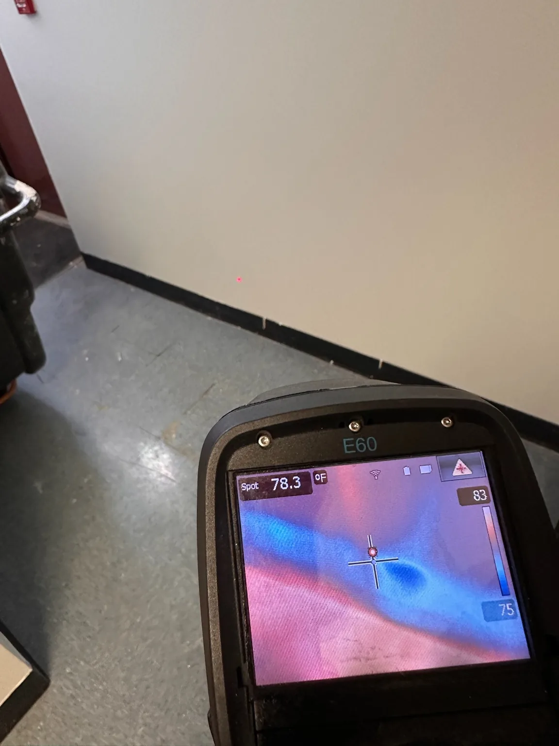
These photographs preserve the relationship between thermal anomalies and the physical work area. The thermal images should be read as temperature maps—not moisture photographs.
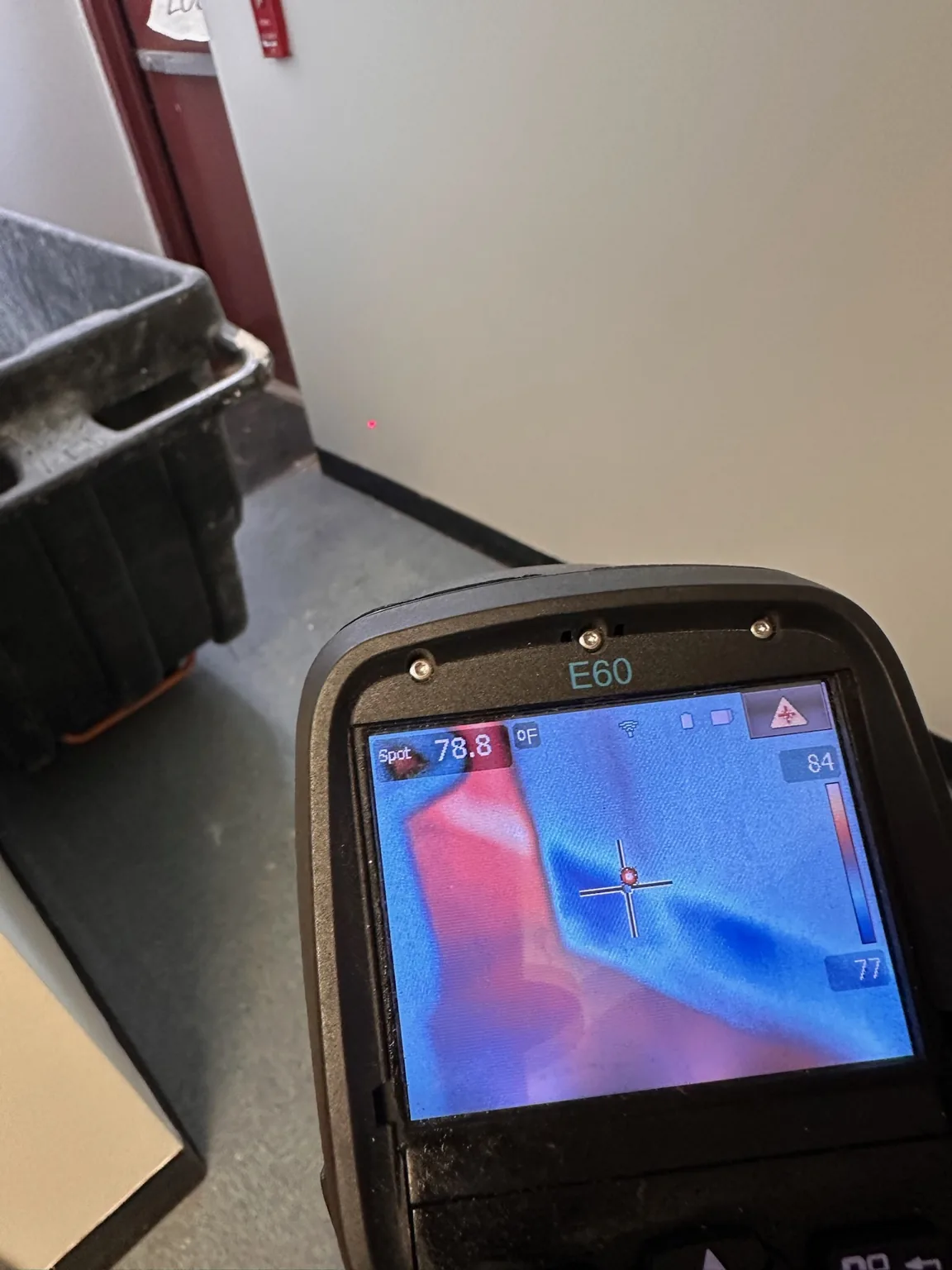
Thermal screening at a wall/floor junction shows a localized temperature anomaly.
FC001-E11Thermal screening at a wall/floor junction shows a localized temperature anomaly.
A second thermal view of the same type of wall/floor temperature anomaly.
FC001-E12A second thermal view of the same type of wall/floor temperature anomaly.
Thermal screening used to map a larger area before or during selective investigation.
FC001-E13Thermal screening used to map a larger area before or during selective investigation.
Thermal anomaly documented while selective demolition exposes the wall assembly.
FC001-E14Thermal anomaly documented while selective demolition exposes the wall assembly.
Thermal view paired with an opened commercial metal-stud wall assembly.
FC001-E15Thermal view paired with an opened commercial metal-stud wall assembly.
Thermal inspection of the floor/wall area after removal exposed underlying assemblies.
FC001-E16Thermal inspection of the floor/wall area after removal exposed underlying assemblies.
Thermal inspection with removed insulation visible in the work area.
FC001-E17Thermal inspection with removed insulation visible in the work area.

Comparative material measurements

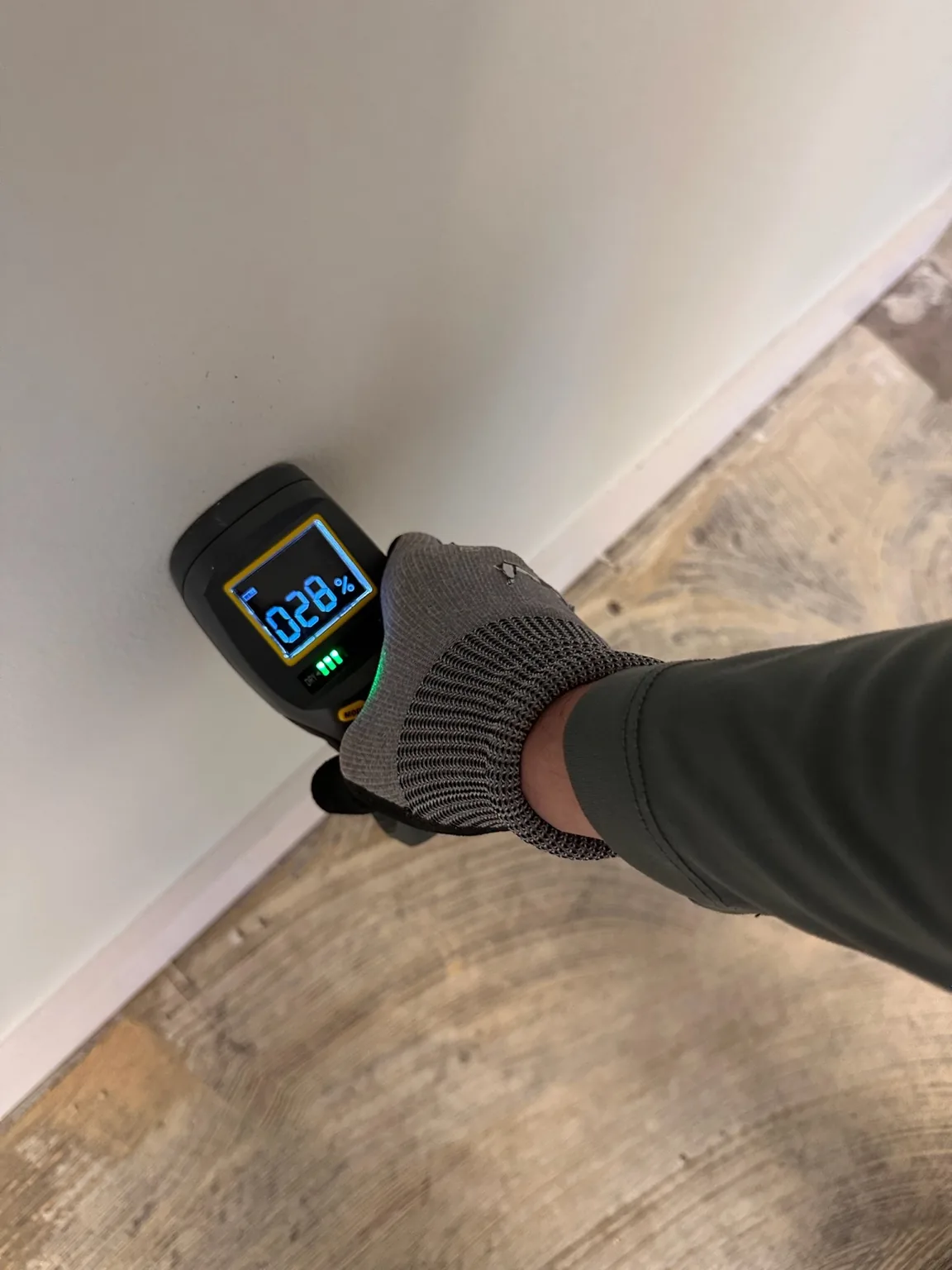
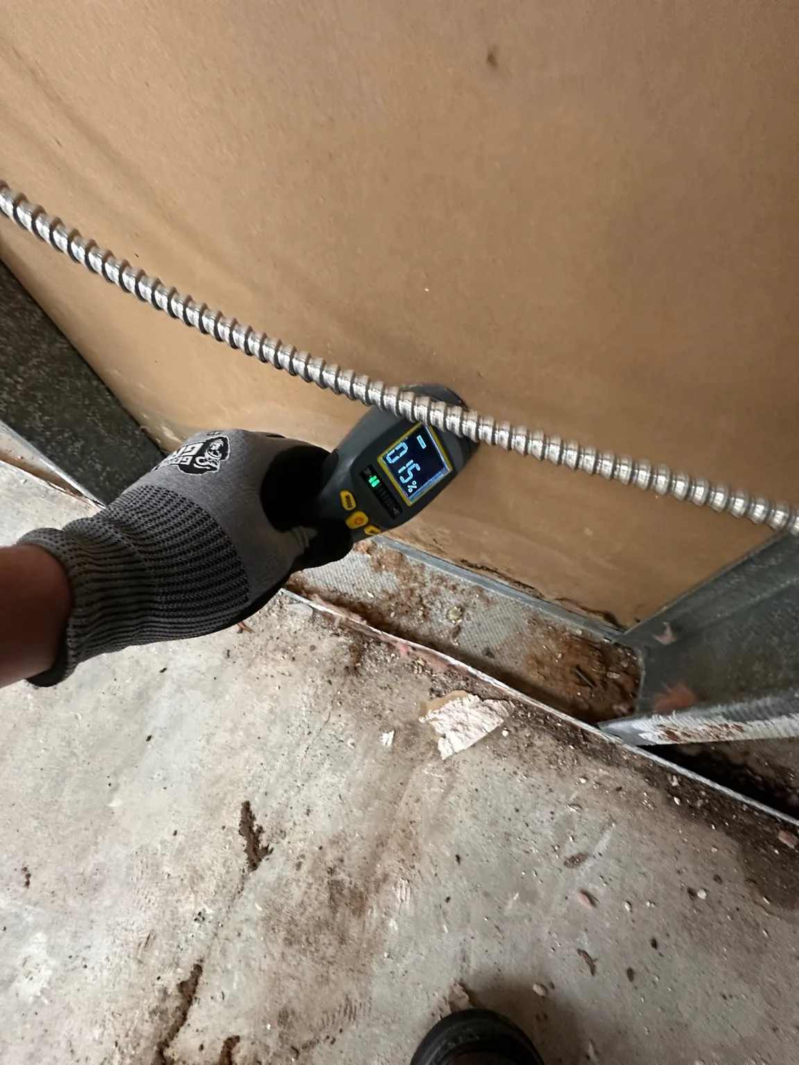
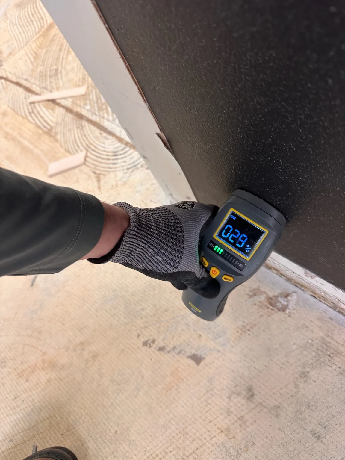
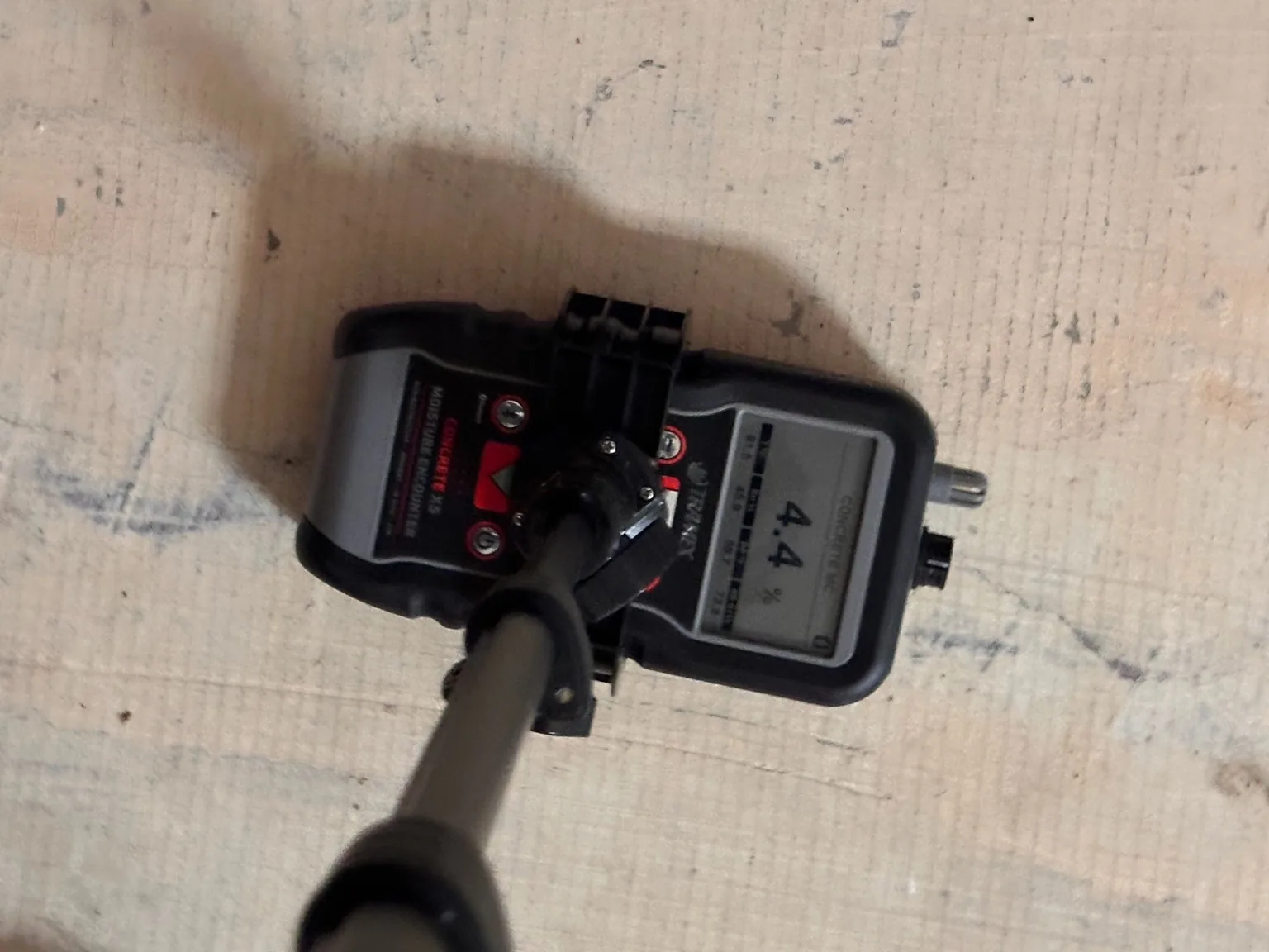
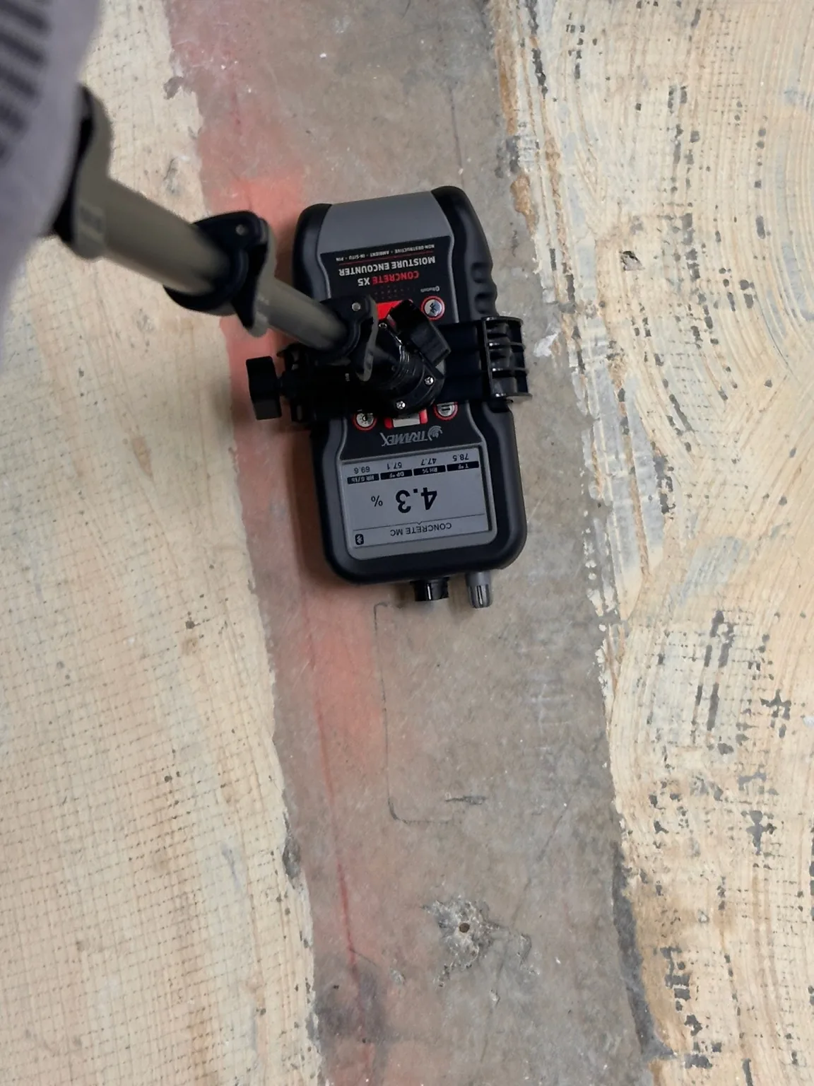
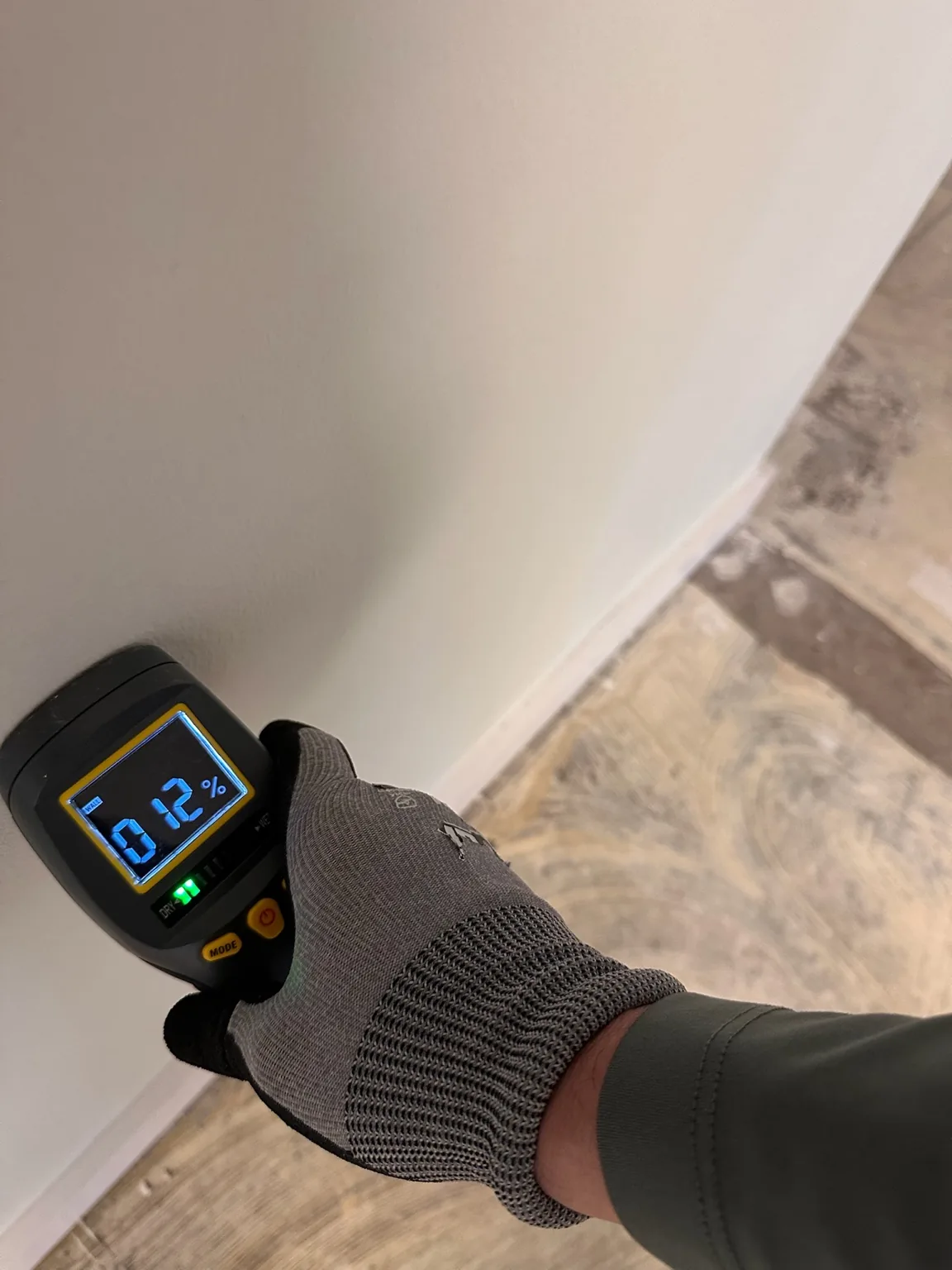
The site preserves meter displays as instrument readings. SDM does not publish a universal wet/dry threshold from these photos because material and instrument context controls interpretation.
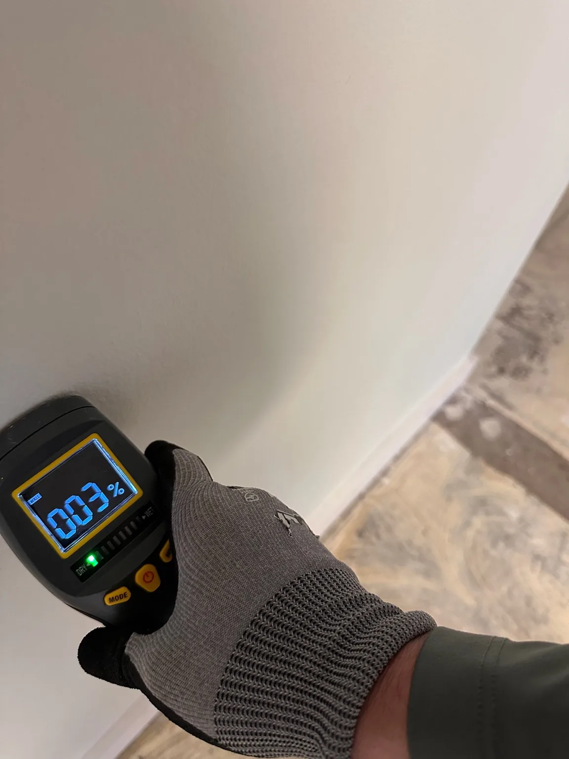
Non-invasive wall screening at one measurement location.
FC001-E08Non-invasive wall screening at one measurement location.
A second non-invasive wall screening point for comparison.
FC001-E09A second non-invasive wall screening point for comparison.
A third wall screening point in the same investigation.
FC001-E10A third wall screening point in the same investigation.
Material screening at an exposed wall assembly after selective removal.
FC001-E18Material screening at an exposed wall assembly after selective removal.
A second material screening point after the assembly was opened.
FC001-E19A second material screening point after the assembly was opened.
Concrete moisture-comparison reading documented at one substrate location.
FC001-E21Concrete moisture-comparison reading documented at one substrate location.
A second concrete moisture-comparison reading at another substrate location.
FC001-E22A second concrete moisture-comparison reading at another substrate location.

Drying-system and psychrometric evidence

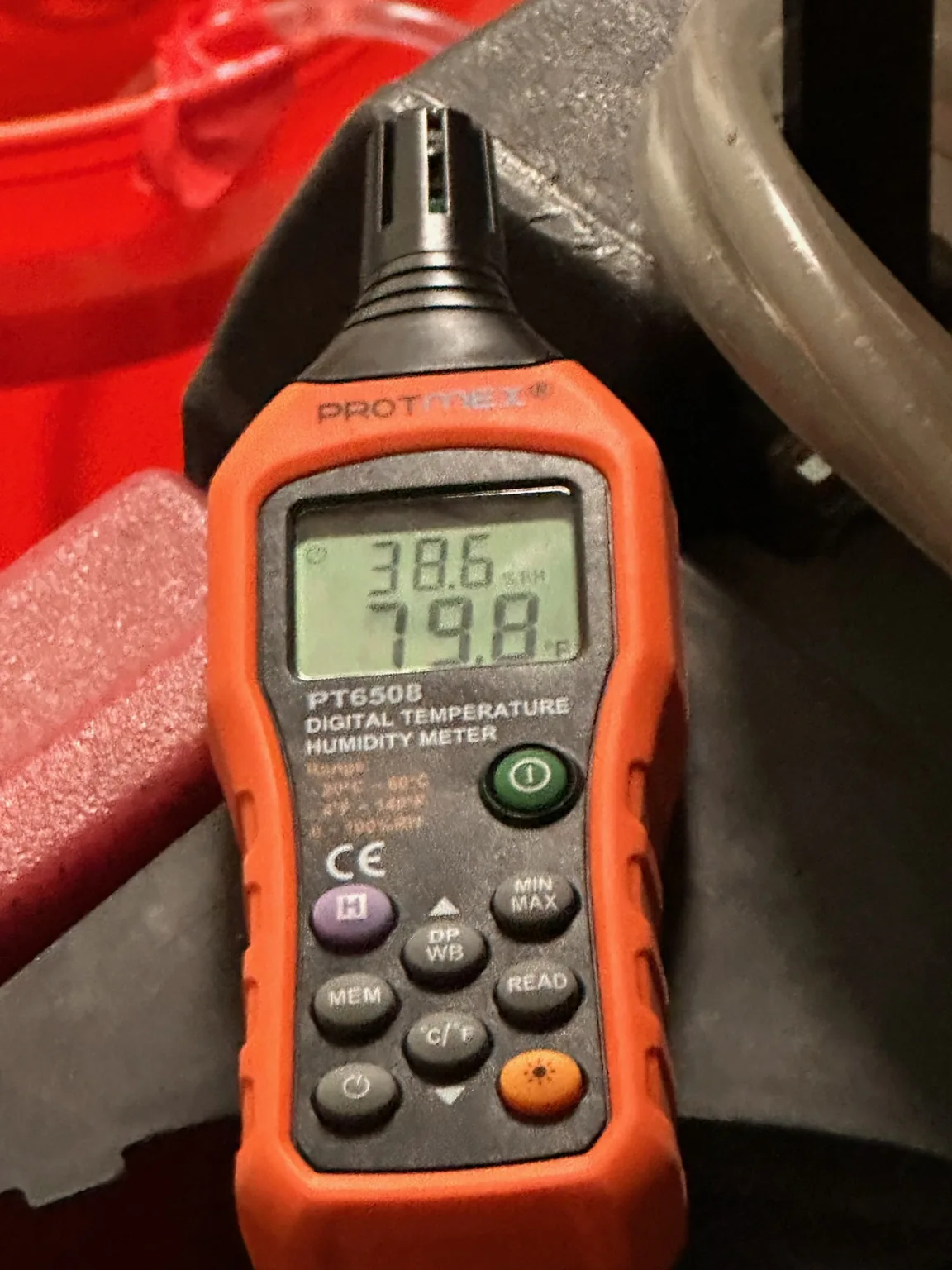
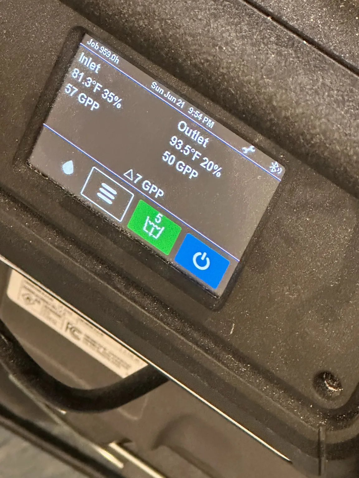
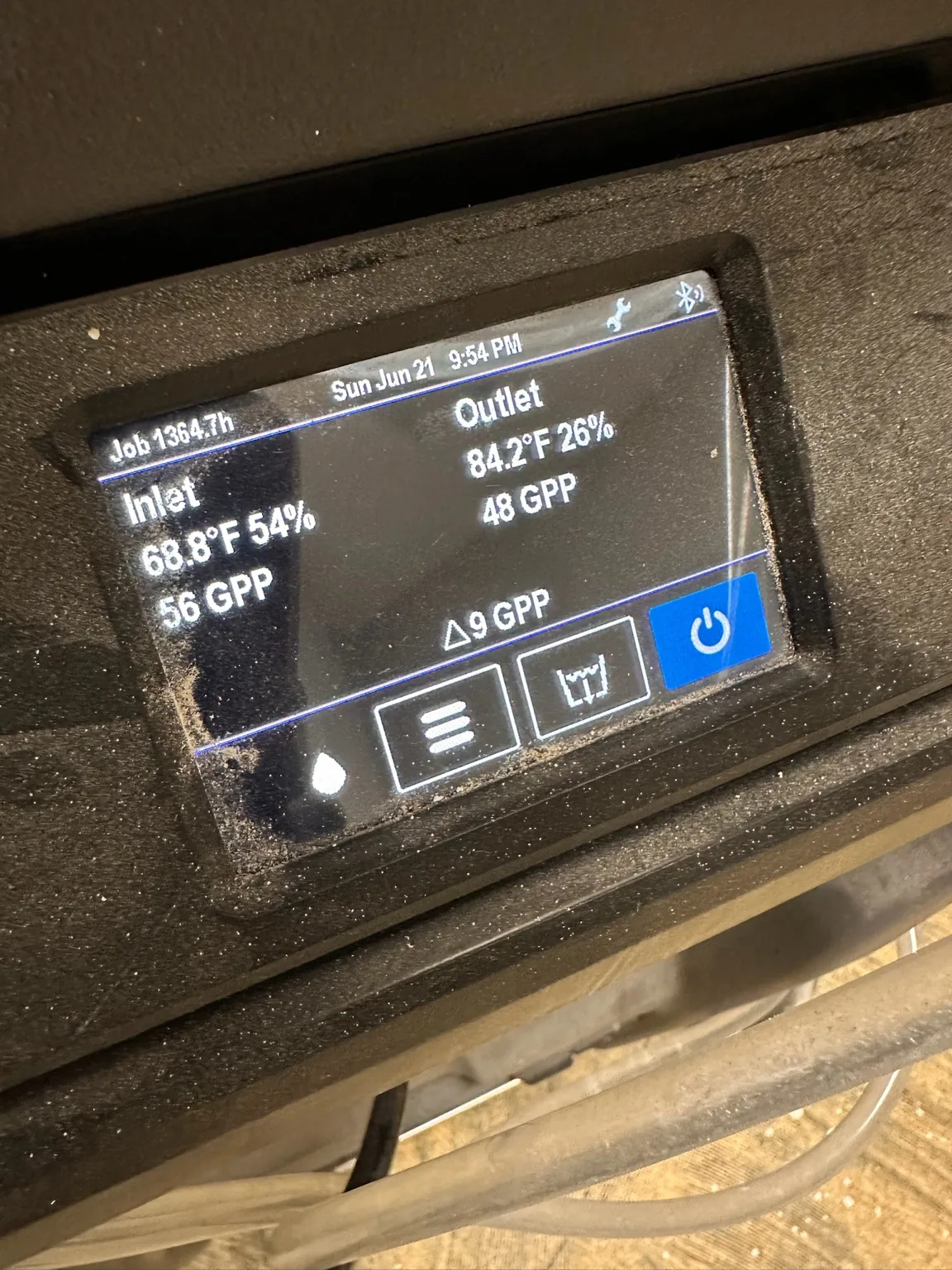
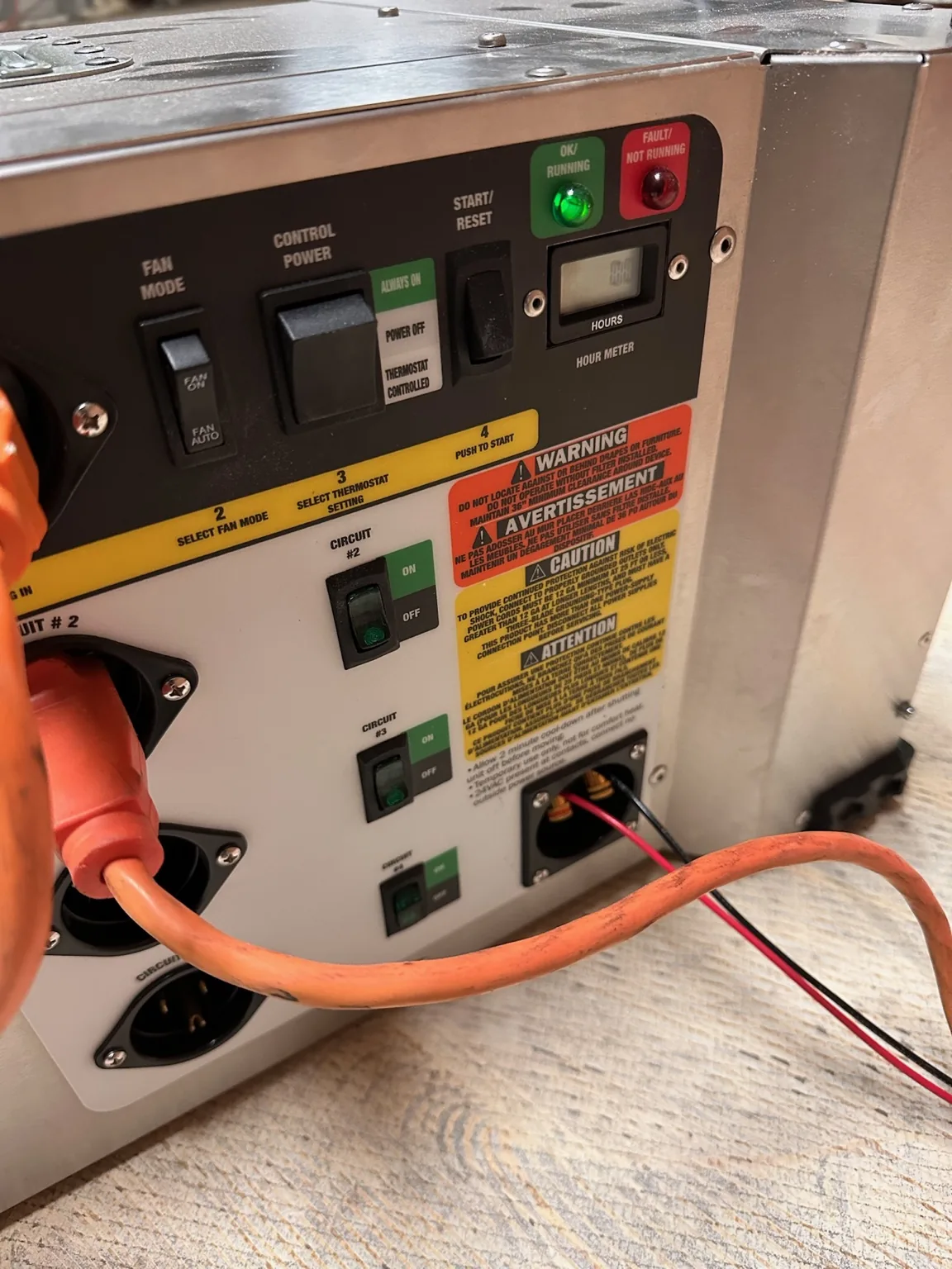
Drying equipment is more useful when its effect can be measured. These records document environmental readings, equipment controls, process airflow, dehumidifier inlet/outlet conditions and condensate handling.
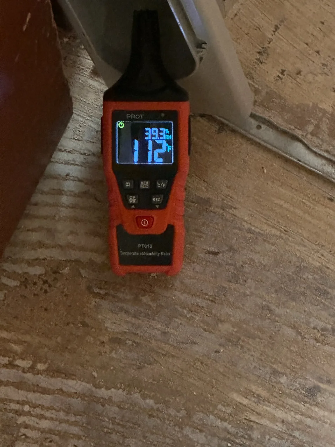
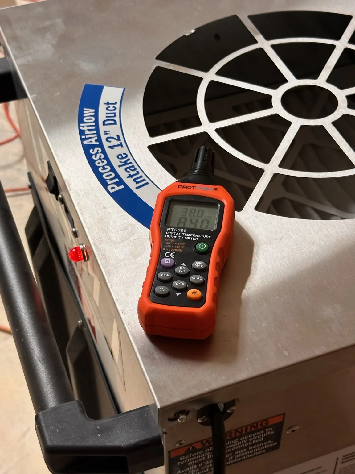
Environmental conditions recorded during active mitigation.
FC001-E01Environmental conditions recorded during active mitigation.
Process-airflow equipment documented with an environmental meter.
FC001-E02Process-airflow equipment documented with an environmental meter.
Field temperature and relative-humidity reading.
FC001-E03Field temperature and relative-humidity reading.
Dehumidifier inlet and outlet psychrometric conditions displayed at the equipment.
FC001-E04Dehumidifier inlet and outlet psychrometric conditions displayed at the equipment.
A second dehumidifier performance screen showing inlet/outlet conditions.
FC001-E05A second dehumidifier performance screen showing inlet/outlet conditions.
Drying equipment operating/control panel documented in the field.
FC001-E06Drying equipment operating/control panel documented in the field.
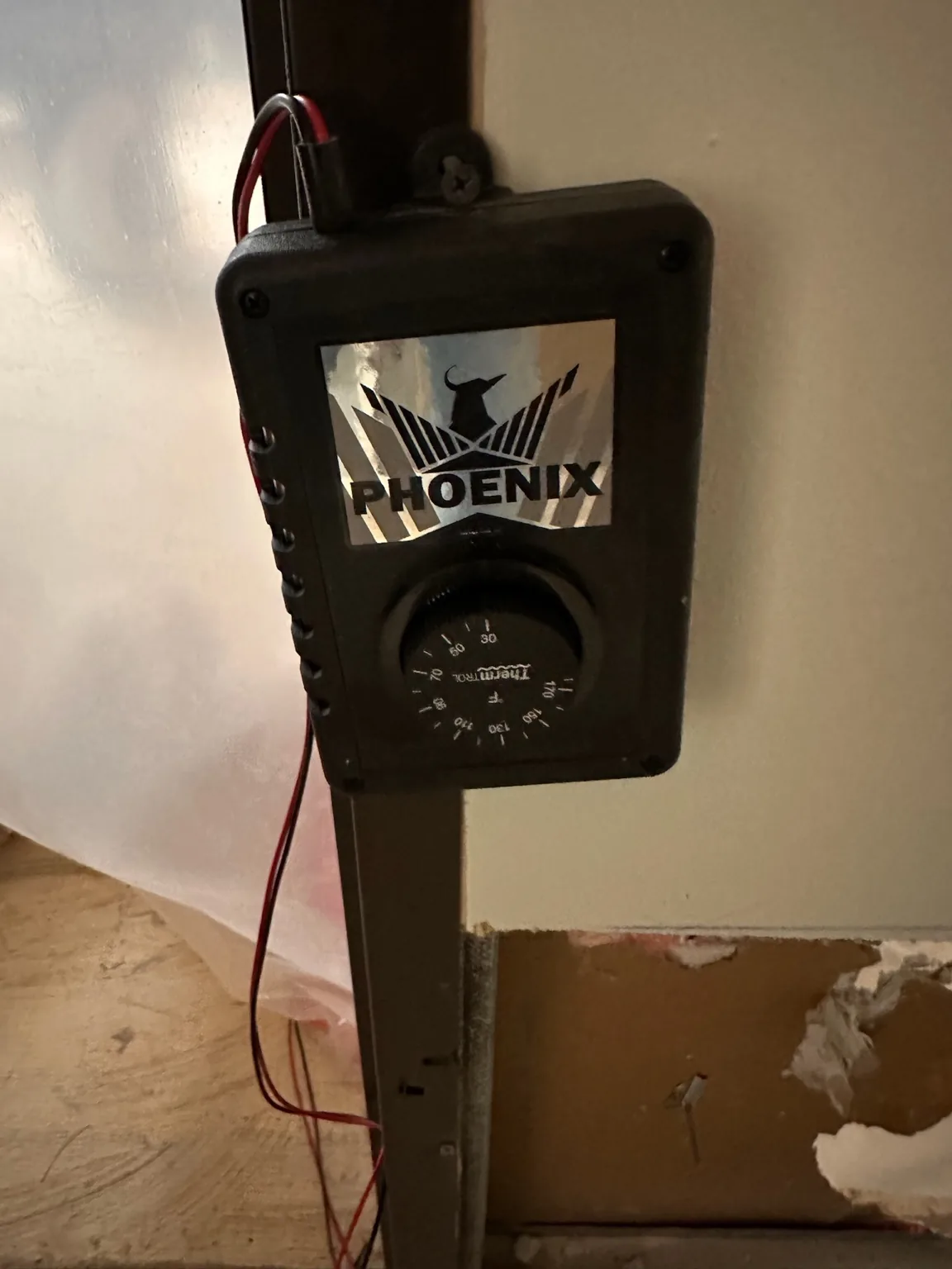
Specialty drying equipment/control documented adjacent to an opened wall assembly.
FC001-E07Specialty drying equipment/control documented adjacent to an opened wall assembly.
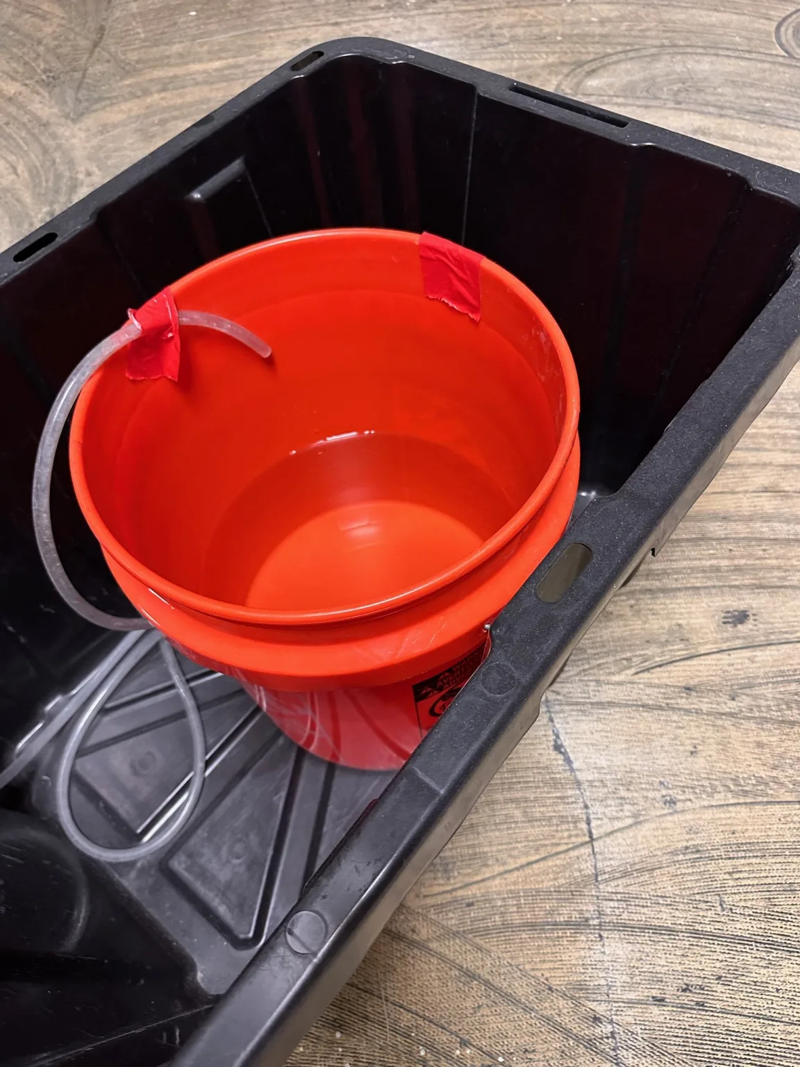
Condensate collection/drainage arrangement documented during mitigation.
FC001-E20Condensate collection/drainage arrangement documented during mitigation.

Source-first technical interpretation

Observed from the field evidence: thermal anomalies, meter displays, exposed commercial wall components, removed insulation/gypsum, drying equipment and psychrometric/equipment displays are visible in the photographs.

SDM interpretation: taken together, the media illustrates a professional workflow in which screening tools guide investigation, measurements are compared, concealed assemblies may be opened when warranted, and drying performance is monitored rather than assumed.

Not established by the photographs alone: the precise source and category of water, the complete affected footprint, final drying goal, final material disposition, insurance scope or project outcome.

Water Damage? Call Now(469) 649-9649 · 24/7 DFWText PhotosSend damage photos